Convert cg-50 to Lithium Polymer Batteries
Posté le 17/06/2020 03:33
Hello
Not sure if the tutorials and tips section is software only, or also hardware.
I wanted to share my experience with separating the concept of AAA batteries from the concept of the calculator. I personally do not like AAAs, even rechargable NiMH ones, and would have really liked CASIO to include some Lithium batteries instead. TI has got this down already in their calcs, but their products are also much more expensive (seriously, ti84+ce for double price of prizm??? no way!) Since even the next generation power graphic 3 calculators are AAA powered, I decided that I had to do it myself.
For the batteries themselves, I used a 2Ah 10mm * 49mm * 34mm battery from Hobbyking, for about $5 USD each. I chose this capacity because it approximately equals the energy in 4 AAA alkalines. However, when laying out the batteries on the case, I realised that I could actually fit 2 LiPo cells! So I did that.
These batteries come with a protection board included, so short-circuit and overdischarge under 3V is no problem.
Of course, I also needed to boost the voltage, since 3.7V is too low to run the calculator. I used an Adafruit Powerboost 500C, which was the most expensive part of the project at $15. A more economical choice would have been the Wemos Battery Shield straight from China, for $1 each. It does not have any protection features, but the batteries themselves are already protected anyway. With this board, I get a steady 5.15V out, which to my annoyance means I have a perpetual 2 battery bars out of 3 filled in the display, but what can you really do...
The Powerboost500C comes with a power LED that shines whenever it is active, but the current draw means that the batteries will drain in a month or so no matter what... not good. I removed the led with brute force soldering, and it still works fine afterwards. If there were no self-drain in the batteries, they would last 20 years now, powering just the boost board! Of course the calculator does draw current even when it is in standby, so this is of limited use, but I also found that removing the blue LED meant that I could see the color of the other LEDs, like charging and low battery, much more easily inside the calc.
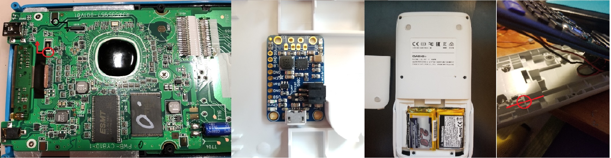
I did not want to have to use a new port for charging, rather I wanted to hijack the USB port already on the calc, which anyway is already used to provide power when it is connected and the batteries are inserted. There was no way I was going to solder directly to the pins of the mini USB connector, (too small!) so I poked around and found two solder pads of components already on the motherboard that were directly connected to the USB power lines. Since so little current (60mA) is ever drawn, I thought it was ok to use these non-optimal source and sink.
The pads i used are in attached picture.
Time to assemble! I planned out the location of the Powerboost board inside the case. I found the optimal position to be the one shown in the picture. The tallest thing on the board, the JST connecter, barely pushes against some SMD resistors on the motherboard, making it a snug fit. And the JST connecter itself can still be used, since it is not against an internal wall/support. Of course, the microUSB connecter cannot be used, but that is by my design anyway.
I also needed to cut out the entire battery compartment to actually fit the batteries. I did not have a dremel or whatever, so I resorted to melting a line through the case with a scrap soldering iron tip (never do this with a good tip!), using a hacksaw to complete the cuts, and cleaning up the edges with a diagonal cutter. Make sure to not dwell on one spot with the iron, or your nice white plastic will burn! Keep the iron moving, with force if necessary. You can roughly trace the lines I used if you also use the same size batteries. This also separates the serial number sticker from the calc, I just replaced it in a different location, but I will be surprised if Casio still gives me warranty repair after this!
Of course, I had to snip the male JST connecter off one of the LiPo batteries and solder it in parallel to the other one, using heat shrink, or else your calculator will surely die! Do not connect in series! Neither the boost part nor the charge part are designed for 7.4V or more.
Now I had to route the wires. Solder a pair of wires from the mini USB pads mentioned before, one to powerboost pin USB, one to a GND. Solder another pair, from 5V and GND to the battery contacts on the motherboard, after removing the contacts already there. Finally, plug in the batteries and see if your calculator powers up! Mine did, to my relief. But closing the case with all the wires was a monumental task. I had to cut many many notches in the internal support walls of the case to fit the wires through. Most of what you have to cut and tape in place will depend on the directions your wires are pointing when they are soldered. Sadly I do not have a picture of them, except for one, which is very important. For a wire to reach the battery contacts on the motherboard, there must be a notch cut in the marked wall.
Most of my notches were either melted with the iron or cut with diagonal cutters. Either way, you will have to route them somehow to close the case successfully.
Finally, I wanted a way to monitor the LEDs on the powerboost board, to see when charging is done and when low battery is detected. Sadly I was not very successful on this front. I initially tried melting a hole in the battery compartment facing the inside of the calc, so when the battery cover is put on there is no modification visible. Unfortunately from that weird angle you will have to hold the calc up to your face and look right through it, and I could only reliably see the yellow charging led, not the green or red ones. This is also why i removed the blue power LED, since it is so much brighter than the rest.
To succeed in this regard, you can either use some sort of optical pipe to redirect the light to the battery compartment hole, or just put a hole on the top edge where the usb/serial connecters are, but this might be a problem for the French models with exam mode LED, as I cannot imagine another LED right next to it will not confuse/anger an invigilator. Either way, I think my measures are sufficient, since another way to test low battery is that your calc will not power on!
And there you have it! Your calc is now Lithium battery powered! There are a couple of benefits to this modification. First, depending on battery size you can easily double or triple the energy stored inside the calc, even after accounting for powerboost efficiency of 95%. Second, if you do not overload on batteries, the calc can become just a little lighter thanks to improved energy density. Third, no one necessarily knows you have modified the power, since nothing has to be visible with the battery cover on. And the usb transfer function is unaffected. Fourth, you get a free 4xAAA battery holder out of it. Of course, there are disadvantages too. I do not think my warranty is still valid anymore, and I do not really know how French Exam Mode rules affect the legality of this mod. At least in the US, there is no problem since many teachers do not even know Casio exists

, and no one cares what kind of ridiculous calculator you use on the SAT/ACT tests as long as it is not clearly internet connected.
Internet connected... hmmmm.... esp8266 over serial, anyone? That would be a fun future project! Or even RGB wowwwwwwwwwwwww
Good luck with your endeavors!
So sorry for the bad photo quality, but 512KB maximum file size! If you want better shots just message
 Fichier joint

Citer : Posté le 17/06/2020 09:22 | #
Wow, that's awesome! Good job on getting it right first try
I'm not too familiar with electronics, but I've used that Powerboost board before and I get the gist of the modification. I didn't think this was even possible. x)
Quick questions: Is battery level detected purely based off the voltage that the battery provide? Is there any heating part that could be a problem?
You can insert your photo into the post with the [img] tag using the link for the attached file. Do you have any photo of the wiring/soldering of the Powerboost?
I'd like to feature a bit of this post on Planète Casio's front page, is that okay with you?
Regarding legal stuff, I don't think this is illegal if you stick to the wording of the exam mode description, but if you're caught in an exam with this modded calculator, you'll definitely be suspected of cheating and in trouble. Especially since changing the exam LED is likely not much harder that changing the batteries :x
By the way, Dark Storm attempted to put an ESP8266 in the case for serial communication a few years back. It is surely doable, though connecting to the 3-pin port without any part sticking out of the case might not be easy.
Citer : Posté le 17/06/2020 17:47 | #
Quick questions: Is battery level detected purely based off the voltage that the battery provide?
Yes, the displayed level is 3 for higher than 5.4V, 2 between 5.4 and 4.9V, 1 between 4.5 and 4.9V, 0 for below that, at least when you select the Alkaline battery type. I don't have the voltage values I recorded anymore, so these are what I can remember. Of course, those skilled with tearing apart the OS can probably get the exact values.
Is there any heating part that could be a problem?
I've verified that the board can deliver 500mA to a constant load or simultaneously charge and discharge the battery at 250mA each without getting warm, probably only the 1A version has any chance of heating up much (the use of smart load-sharing is not good anyway, since the load-shared output stupidly connects to battery voltage rather than boosted 5V when not charging). At any rate the calculator never demands more than 60mA from the boost side even when overclocked, and charging over USB with 500mA does not bother the TPS4056 on the charge side. The only real problem would be if the batteries are not big enough to allow 500mA charge rate.
A feature would be great, thank you! The news articles here are so informative.
I will try some images now, all from the album https://imgur.com/a/3ZzNEgC
For some reason I cannot successfully make an imgur account, so if these get randomly deleted just let me know
Overall shot showing connections to the motherboard
Shot of case wiring with no annotation
Shot of case wiring, with approximate final routes of wires
Shot of case wiring, with blue circles marking where cuts were made. The most lower right cut is absolutely necessary to get wires to the battery contacts, it just so happens my battery hole intersects it anyway, so I didn't need to specifically cut it.
Just the big hole where the battery holder used to be
Closeup of the powerboost board position and soldering itself
Wires in their assigned routes, and a note that the battery contact wires must be kept on the outside of the blue capacitor for the case to close successfully.
Shot of the hole I made to see the LEDs on the powerboost, which doesn't work very well
The case does indeed close all the way! It took a lot of work to get to this point.
The finished product
Edit: hmmm... no pictures, only blank hrefs for me. I do not know how to fix this, but at least the links to each image on imgur still work
Edit: fixed the pictures, thanks! Put them at one eighth size on this page because they are so big
Citer : Posté le 17/06/2020 18:22 | #
Wow, that's some detail! Thank you very much. You don't have images because you have put in the [img] tag a link to the imgur *page* with the image instead of directly linking to the image, which is what [img] expects.
I'll try to put up an article next week. People at the French division of Casio read the news so... who knows, maybe that'll inspire them!
Citer : Posté le 17/06/2020 22:40 | #
Wow, very clean. Quite a nice job :o
By the way, Dark Storm attempted to put an ESP8266 in the case for serial communication a few years back.
Indeed, I tried to put an ESP8266 (ESP-01 without headers) into my Graph 35+, but the module was a very cheap one, it worked once in a while on my arduino and never on the calc. And at that time I was not enough experimented to reprogram the firmware to make it more reliable.
Even though, if you make it, you can use Webcalc, an HTML interpreter by Lephenixnoir. It's definitely not permissive, but you may program a kind of proxy to display a more condensed version of classic webpages. Definitely a great hacking project!
——— Edit ———
The program Webcalc can be found here → https://www.planet-casio.com/Fr/programmes/programme2849-1-webcalc-lephenixnoir-utilitaires-add-ins.html
And BYW Lephe, if you write a news about this project, maybe you can resize and host on PC the pictures, to remove the dependency on imgur
Citer : Posté le 20/06/2020 00:59 | #
Small note, it turns out that a 6mm push button fits almost perfectly in the space right behind the hole, with a long enough shaft accessible from the outside... very useful for expansion!!
Ajouté le 20/06/2020 à 05:04 :
Ah, I found where I recorded the voltage display levels for alkaline batteries. On my calculator. I am surprised at myself too.
3: > 5.3V
2: 4.8 - 5.3V
1: 4.2 - 4.8V
0: < 4.2V
Citer : Posté le 24/06/2020 14:20 | #
Here's the topic on the front page : Convertir sa Graph 90+E des piles à une batterie LiPo !
It's somewhat short but I wanted to leave some details for people to discover here. Thanks again for sharing the detailed process, we never did that before